Aquarium-LED-Light-Controller based on Raspberry Pi
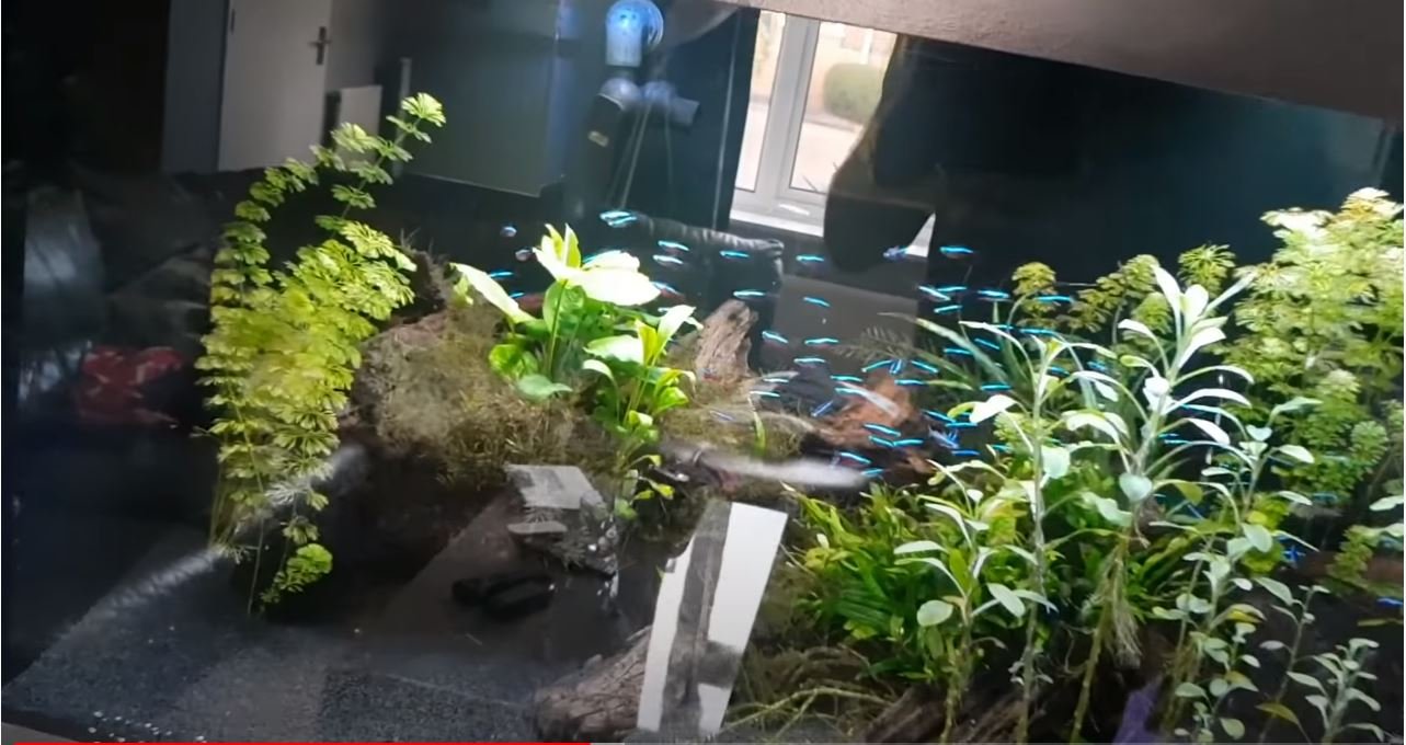
An aquarium coffee table is good for hobby and work.
One of the most important components of an aquarium is proper lighting (among other things).
There is a lot of literature on the internet on the subject, from the very simple on / off timer switch to the sophisticated sunrise-sunset-season controller.
Step 1: start
Neon lights are widespread, but only allowed with the on / lighting of an aquarium.
In the event that some wants sunrise sunset control, LED lighting is a must.
LED strips are easily controllable by PWM (pulse width modulation) signals, they can be protected with up to IP67 ...
There are a lot of aquarium lighting systems that control the amount of lighting by varying the LED strip power. Even the sunrise-sunset-season controllers use this, but in a time-controlled manner (they increase the power from zero to maximum and then to zero ...).
These systems consist of the following three components: a power supply, a controller and the LED strips. The only thing I can find is a really light controlling system that measures the actual light level and the LED bar makes use of the light level.
This is "only" the use of a light sensor.
This was the point when the idea of the "Aquarium LED Light Controller with RPi" was born.
Step 2: true lighting control
The starting points of an easy to use, programmable light
Controllers were as follows:
-Complete lighting control with PWM able to control from 0-100%
-Exact light measurement (no LDR or other wrong techniques)
-Easily programmable via PC or smartphone
-Can be used with almost any LED lighting or Insead controller available
-Exact timing (RTCs do not suffer long-term time shift)
The first 4 points indicate a microcontroller based system, but the 5th point requires an internet connection and NTP protocol. The choice to use Raspberry Pi was the need for quick, easy development and easy expandability.
Step 3: main components
First, the light sensor was chosen. The BH1750 based light sensor module communicates via I2C bus, measures with a very large range and high accuracy and is a cheap one.
Second, the PWM signal - comes from the RPi - needs to be amplified in order to drive the LED strips. A simple "no name" 3-channel LED amplifier / repeater was chosen.
And finally - the Raspberry Pi - can each of its sub-types (model A-B-B + -B2-B3-zero ...). In fact, the first edition of the RPi Model B (with 256MB of RAM) was used as it was with a 4GB SD card on hand.
The controlling software runs on it, with its own graphical user interface, so the development on the RPi found no other programming device needed.
Since no one wants a monitor next to an aquarium, there is a need for remote access to the RPi. The actual screen of the RPi can be seen through VNC connection from the PC or smartphone.
Step 4: hardware
The following components are required for lighting control:
-Raspberry Pi
-Light sensor BH1750
-LED amplifier
-Fuses
-Thermal switch
-12V power supply
Fuses are used to protect the 12V line (each segment of the LED strip is fused so if one segment goes short then it will total less than the power supply will not cause).
Thermal switch normally closed and glued with heat sink for the LED strip (with thermal paste). The temperature of the heat sink rises above 50 ° C then simply opens the circuit and protects the LED strip from overheating. KSD9700 type (50 ° C) was used. If the temperature rises above 50 ° C, the thermal switch opens and remains open until the temperature drops below 35 ° C.
This function is only for security, under normal conditions, under those it does not work (open) at all.
A 12V power supply is usually used one, 12V / 6A.
Step 5: software
As already mentioned, the software runs on the Raspberry Pi.
The concept was easy and quick to develop the controlling software.
Since the aquarium light system was first set up, it has only been done occasionally (1 to 3 times), the appearance of the software is minimalist: only the most important information is displayed and the input elements are only smartphone-friendly buttons.
The software was written in Python Tkinter used as the graphical user interface.
The program starts after the Pi boots, reads its settings from the config file. In order to have the exact time the Pi needs internet connection (current time comes from Network Time Protocol).
Remote connection is via Vnc (virtual network computing) protocol via x11vnc, no encryption, no password, nu
r easy remote display and control.
The light control has 9 time steps, each step has its illuminance setpoint. The intermediate points (between two setpoints) are calculated with linear interpolation.
There are 2 additional timers, e.g. B. for taxes can. Pump, CO2 supply ...
The software is what you see, everything is obvious, with the (necessary) information shown. The basic resolution is set to 1024 x 768, suitable for mobile phone screens.
The control scheme is a simple integration of controller with a dead zone. The power level knob has 1000 steps, so 0.1% is the slightest change in output, which is perfectly fine enough.
Raspberry Pi only has one hardware PWM output that is used in this project. The Maxium PWM frequency (with 1000 step resolution) is 9600 Hz, but real experiments (with oscilloscope) showed that anything above 1000 Hz is useless (simply the LED strip is not fast enough), was actually set at 960 Hz.
If the current time corresponds to a time setpoint, the program saves the actual power level in the configuration file.
If the light sensor fails, a flashing red LED shows this, but the light control continues with the previously saved energy level data.
Step 6: arrangement, construction
The light sensor is a bare PCB module (as can be seen) that proved very difficult to make waterproof, so actually the light intensity of the water surface is being measured.
Some additional notes: earlier, the aquarium had neon lights switched on for 10 hour intervals.
The illuminance on the surface was 15800 lux, so the luminous exposure was approx. 158000 lux.h daily.
The LED lighting must produce roughly the same bright exposure as the neon lights, with sunrise-sunset control.
The samples actually used were taken from:
http: //www.pveducation.org/pvcdrom/Properties-of -...
To sum it up: the aquarium looks really different with sunrise when sunset is used, nature wakes up in the morning ... the whole thing looks better ...
Step 7: code, setup
Rasbian Jessie served as the operating system, so download it first:
https://www.raspberrypi.org/Downloads/Raspbian/
Boldly write Jessie picture on the RPi SD card, connect an HMDI monitor, a keyboard, a mouse, an ethernet cable and plug the SD card into the Raspberry, then turn it on.
The following steps are required to set up the light controller:
-Start a terminal window
To enable the I2C interface on the Pi, enter:
Sudo Raspi-config
Then go to the menu: Advanced / I2C / yes
Then quit Raspi-Config.
A couple of changes in the config.txt file is needed, so type:
Sudo Sed -i / ^ # Hdmi_force_hotplug / Hdmi_force_hotplug = 1 / g '/boot/config.txt
Sudo Sed -i / ^ # Hdmi_group / Hdmi_group = 2 / g '/boot/config.txt
Sudo Sed -i / ^ # Hdmi_mode / Hdmi_mode = 16 / g '/boot/config.txt
Copy the "Aquarium_LED_light_control.py", "LED_PWM_wiringpi.py" and the "Light_control.ini" files to / home / pi.
("Aquarium_LED_light_control.py" is the main program, while "LED_PWM_wiringpi.py" is used to test. The tests can be carried out via directly changing the power while changing the illuminance to see. "Light control.ini" file is necessary to the main program executed.)
Then type as follows:
Sudo apt-Get Update -y
Sudo apt-Get Upgrade -y
Sudo apt-get install -y-python-dev-python-pip
Sudo apt-get install -y python-smbus i2c-tools
Sudo pip install wiringpi2
Sudo apt-get install -y python-tk
Sudo apt-Get Install x11vnc -y
Sudo cd /home/pi/.config/autostart
Echo [Desktop Entry]> x11vnc.desktop
Echo Encoding = UTF-8 >> x11vnc.desktop
Echo type = application >> x11vnc.desktop
Echo Name = X11VNC >> x11vnc.desktop
Comment on Echo = >> x11vnc.desktop
Exec Echo = x11vnc-forever - Display: 0 >> x11vnc.desktop
Echo StartupNotify = False >> x11vnc.desktop
Terminal Echo = False >> x11vnc.desktop
Echo Hidden = False >> x11vnc.desktop
Echo [Desktop Entry]> lxterminal.desktop
Echo type = application >> lxterminal.desktop
Echo Name = LEDaqua >> lxterminal.desktop
Exec Echo = Lxterminal -e 'Sudo Python /home/pi/Aquarium_LED_light_control_wiringpi_fullscreen.py' >> lxterminal.desktop
Echo StartupNotify = False >> lxterminal.desktop
Echo Hidden = False >> lxterminal.desktop
Sudo reboot
After the restart the light controller is ready for use, with or without a monitor, can be accessed via VNC.
Have fun!
